For Part I, covering the new combustion system, direct injection, and active fuel management: click here.
For Part II, covering the valvetrain, exhaust, and cylinder heads: click here.
Finishing what we began with the first two installments of GM’s fifth-generation small-block LT1 V8 engine, we finalize by discussing what composes the engine’s block itself, along with its forged crankshaft and lubrication systems.
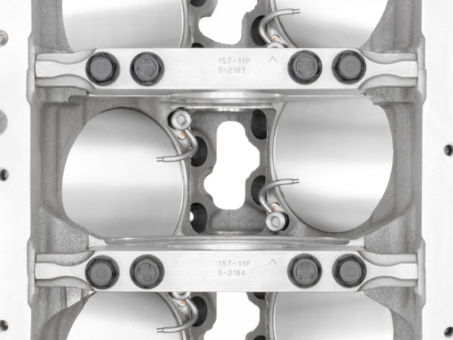
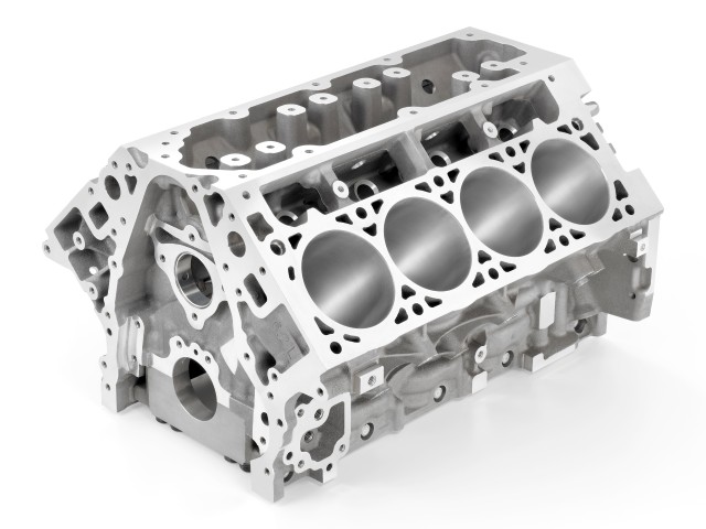
Appropriately, the block is 319 precision cast aluminum (high quality stuff), with 103.25 millimeter bores featuring cast-in-place liners. And what used to be powdered metal main caps are now a flexible nodular iron (AKA ductile iron). There are also new engine mount bosses (notches or grooves) unique to the block.

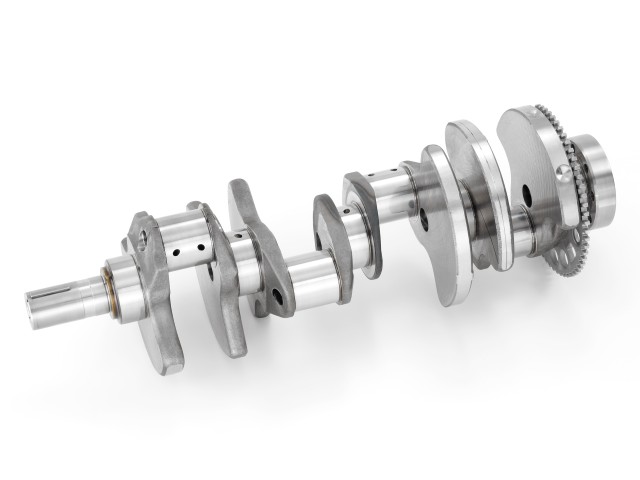
To survive the inevitable thrashing, the crankshaft of the LT1 is not only forged steel, but is put together with optimal windage in mind. Windage is drag that occurs due to oil splashing up to the crankshaft at higher RPMs or from high-G cornering. Both the main bearings and rod bearings are composed of a polymer coated bi-metal material, while the three-piece upper thrust bearings are welded together with lasers. And lasers are always cool.
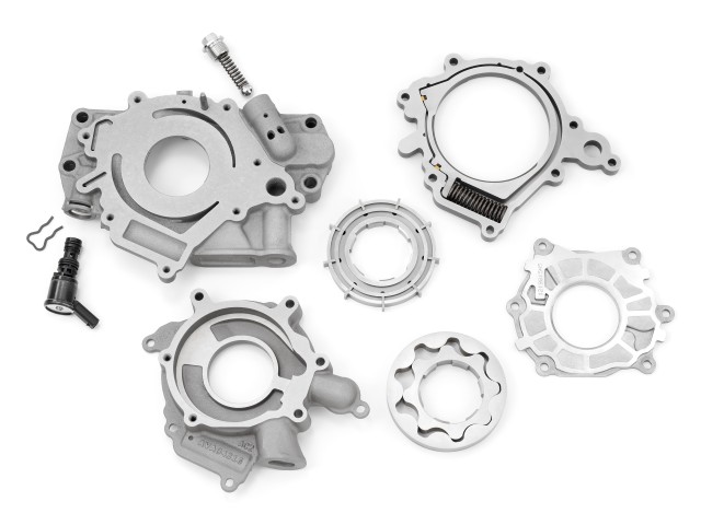
Meanwhile, the LT1 crankshaft-driven lubrication system has its own set of wonders. A variable-displacement oil pump allows the engine to have proper oil pressure on the bearings. Operating in tandem with the engine’s Active Fuel Management system, the lube circuit provides a very efficient level of pressure at low RPMs, while the pressure heightens as the driving gets more aggressive.
There will be an oil-spray piston cooling system in the new small-block, in which eight oil-spraying jets in the engine block drench the underside of each piston and the surrounding cylinder wall with an extra layer of cooling, friction-reducing oil. The system, which is only found in the LSA and LS9 engines today, will be standard on all fifth-gen small-block engines, according to GM. In effect, the oil spray reduces piston temperature, which promotes extreme output and long term durability. The extra layer of oil on the cylinder walls and wrist pins also dampens noise, for a quieter driving experience.

There’s also an optional dry-sump oil system for the serious performance driver. Yes, both wet and dry sump oil systems will be available.
The LT1’s dry-sump system draws liquid oil and any resulting mixture of oil, air and crankcase gases from the bottom of the engine oil pan through an internal scavenge return tube. This mix is then pumped to the top of the dry-sump tank (mounted in the engine compartment, but outside of the engine itself). Within the tank, the oil mixture is variably spilled out on a spiral-shaped internal baffle where the contact and flow about the internal surfaces of the tank promote separation of air and gasses that are caught in the oil. These gasses are directed by a Positive Crankcase Ventilation (PCV) system through a series of baffles and tubes back to the combustion chamber to be burned.
With the oil free of excess air, it is then directed down the walls of the tank to collect in the 10.5-quart reservoir (wet-sump applications will feature a six-quart capacity), conditioned and ready for use. The second stage of the dual-stage gerotor pump then draws the prepped oil from the tank and pressurizes it, feeding it to the engine via the oil filter and oil cooler. The routing of the engine oil to and from the dry sump reservoir also provides the benefit of passive oil cooling.
The patent-pending PCV system itself is quite modern as well. With its domed rocker covers, the PCV enhances oil economy and oil life, while reducing oil consumption. It also contributes to low emissions for the new engine.

The rocker covers increase their importance by holding direct-mount ignition coils for the coil-near-plug ignition system. Between the individual coil packs, the domed sections of the covers feature baffles which control and separate oil and air from the crankcase gases – about three times the oil/air separation capability of previous small-block engines. Each cover features and inlet and outlet path for the crankcase gases, with the separated oil dropping back onto the engine within the covers and the remaining air/gases circulated back into air intake stream for combustion. The system also prevents moisture from accumulating in the engine. Lastly, the domed rocker covers make the fifth-gen small-block instantly recognizable over previous GM V8 engines, if you know what you’re looking at.
It will be this engine, with a preliminary 450 horsepower — though it is expected to be higher when the official numbers are in — that will be the heartbeat of the all-new, seventh-generation 2014 Corvette base model. Expect more LT-engine family variants as the C7 matures into its product life cycle, which will make its official debut January 13 during the 2013 North American International Auto Show in Detroit, MI.


Comments
wow this motor is so high tech now, it seems so long ago when we had the old 350 chev motor and how ancient it seems now, when you read this. Makes me wonder whats next for the LS motor, go chev go !
Awesome article.
Still trying to wrap my head around how the valve covers are tied into separating the oil from the crankcase gases. Maybe I’m making it too complicated in my head.
Maybe its like when they added vent holes in the ls6 lower block to move internal gasses back and forth, some early ls motors pushed oil into the pcv , now with intake and exhaust in valve covers for breathing, no oil can get into the pcv ?
Awesome piece of engineering , but too bad we don`t get a DOHC 4-Valve head here in 2013 !
Why are there no classic end elevation drawings available to compare with the wonderful ones always found in the front of the shop manuals in the fifties and sixties? Much more informative than the overly complex isometric renderings.
So does this block have different engine mounts, or just extra ones? If I wanted to swap this engine in place of my gen IV v8, would my existing motor mounts work?